| University | National University of Singapore (NUS) |
| Subject | OTH396 Civil Engineering Assignment |
OTH396 BTech Engineering Bridging/Preparatory Unit: Civil Engineering
Question 1
Using the method of joints, determine the force in members BE, AD and BD for the truss shown in Figure Q1.

Buy Custom Answer of This Assessment & Raise Your Grades
Question 2
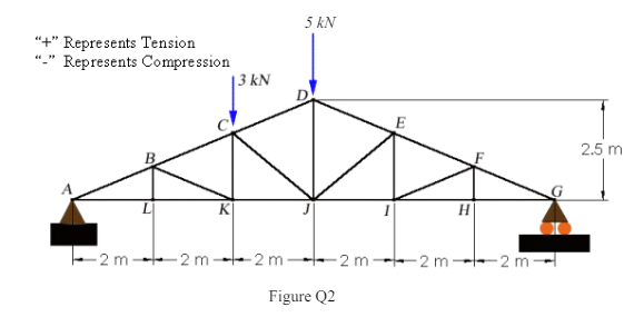
Determine the force in members DE and DJ of the truss shown in Figure Q2
Question 3
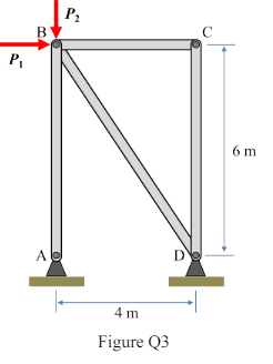
Determine the force in members AB, BD and BC of the truss shown in Figure Q3.
Question 4
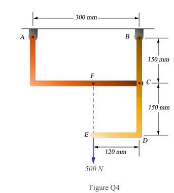
Determine the components of the reactions at A and B:
a) if the 500 N load is applied as shown in Figure Q4,
b) if the 500 N load is moved along the line of action and is applied at point F.
Question 5
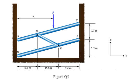
A vertical load P of magnitude 750 N is applied to member ABC as shown in Figure Q5. Members ABC and DEF are parallel and are placed between two frictionless walls and connected by the link BE. Knowing that a = 0.75m, determine the reactions
(a) Ax at point A,
(b) Cx at point C,
(c) Dx at point D,
(d) Dy at point D, and (d) Fx at point F.
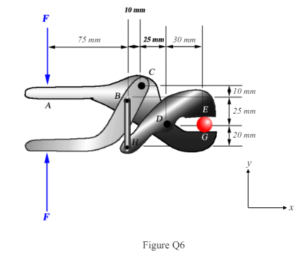
Question 6
A force F is applied to each of the handles of a compound-lever cutting tool shown Figure Q6. Determine the cutting force between E and G, the vertical component of pin reactions on member ACDG at C and D. Also determine the tension or compression in member BH.
Question 7
Knowing that mB = 18 kg and mC = 10 kg, determine the magnitude of the force P required to maintain equilibrium. (Use g = 10 m/s2).

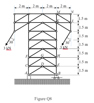
Question 8+
Determine the forces in members FC, CD and KL of the truss in Figure Q8.
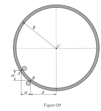
Question 9+
A uniform thin ring of radius R = 200 m and weight W is lodged between two pegs at A and B, as shown in Figure Q9. Neglecting friction, determine the distance 𝛿𝛿 and the normal reactions at pegs A and B in terms of W corresponding to equilibrium when α = 40 mm.
Question 10*
(a) Calculate the tension T in the rod BD and the forces that act on each member of the pin-connected structure in Figure 10.

(b) The pin D of the structure in part (a) may be placed anywhere along member CE. Determine the “best” location for D and give reasons for your choice.
Hint: Determine the forces in member AB and the forces that act on pins C, D and E. Tabulate or plot these forces as a function of distance x from pin E to D and choose a location for D. A B E D 30o C 0.5 m 6 m 10 kN 1.5 m 6.
Question 11+
The truss in Figure Q11 carries a load P = 60 kN applied at joint M. Answer the
following questions neglecting the weight of the construction:
a) Determine the reaction forces at the supports at A, B and C.
b) Identify all zero-force members.
c) Calculate the axial force in EF and FL.
d) Determine the axial forces in TU, QR and BO.

Question 12*
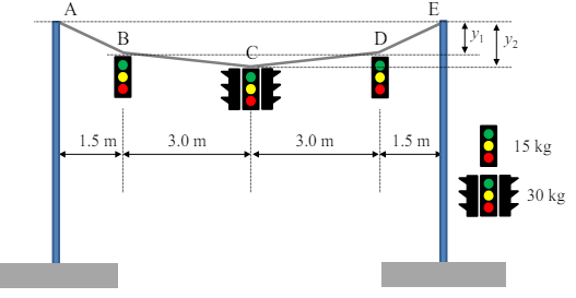
You are the engineer in-charge to design a new hanging traffic light system, as shown in the figure below. The system can be idealized as a cable subjected to multiple point loads.
To provide vehicle clearance, the mid-span sag (y2) must be less than 1.0 m. The client also requests that you use a cable with a maximum allowable tension of 1000 N.
Find the minimum cable length that satisfies the maximum sag and tension
requirements. Report the sag at all loading points according to the cable length you choose (g = 10 m/s2).
Hint: y2 and y1 have a certain relationship that must be satisfied for equilibrium.
Stuck with a lot of homework assignments and feeling stressed ? Take professional academic assistance & Get 100% Plagiarism free papers
Are you struggling with your OTH396 Civil Engineering Assignment? you do not need for take stress. we provide assignment writing services in singapore for engineering students. engineering students can get essay help, coursework help, case study help at cheap rate.

Looking for Plagiarism free Answers for your college/ university Assignments.
- CH2123 Assignnment : Fugacity, VLE Modeling & Henry’s Law Applications
- BAFI1045 Assignment -Constructing and Evaluating Passive and Active Portfolios Based on the Straits Times Index (STI)
- PSB501EN Assignment 1: Engineering Systems Integration: A Multi-Technique Approach to Mechanical Analysis
- FIN2210E/FIN2212E Group Assignment: Financial Risk Management Analysis of Bursa Malaysia Companies
- FLM101 Assignment: A Cinematic Dissection: Stylistic Elements and Their Thematic Significance
- Assignment: Transforming Talent in the AI Era: From War to Wealth through Ecosystem Innovation
- COMP 1105 Assignment: Health-Focused E-Commerce Website: A Web Technologies Project Using HTML5, CSS, and JavaScript
- Assignment: Machine Learning in Robo-Advisory Services: Evolution, Applications, and Future Trends
- OMGT2229 Assignment: Quantitative Forecasting, Economic Order Analysis, and Strategic Sourcing Decision-Making for JB Hi-Fi
- Assignment 2: Corporate Finance and Planning: An In-Depth Financial Analysis of Company