| University | National University of Singapore (NUS) |
| Subject | OTH396 Civil Engineering |
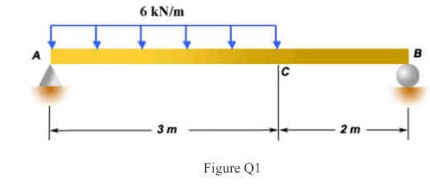
Question 1
A solid rectangular cross-section beam, 80mm wide by 120mm deep, is loaded as shown in Figure Q1. Calculate (a) the distance of the location of the maximum bending moment from point A and (b) the magnitude of the maximum bending stress in the beam.
Hire a Professional Essay & Assignment Writer for completing your Academic Assessments
Native Singapore Writers Team
- 100% Plagiarism-Free Essay
- Highest Satisfaction Rate
- Free Revision
- On-Time Delivery
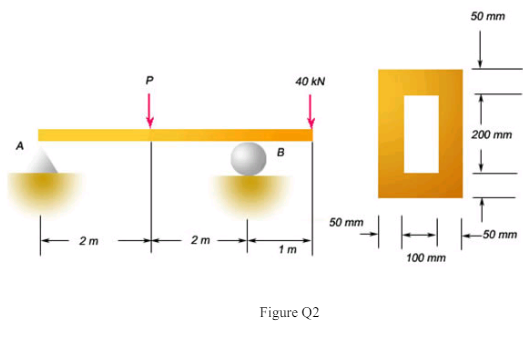
Question 2
A box beam supports the loads shown in Figure Q2. Compute the maximum value of P if the allowable stress σall = 18 MPa, and P > 20 kN.
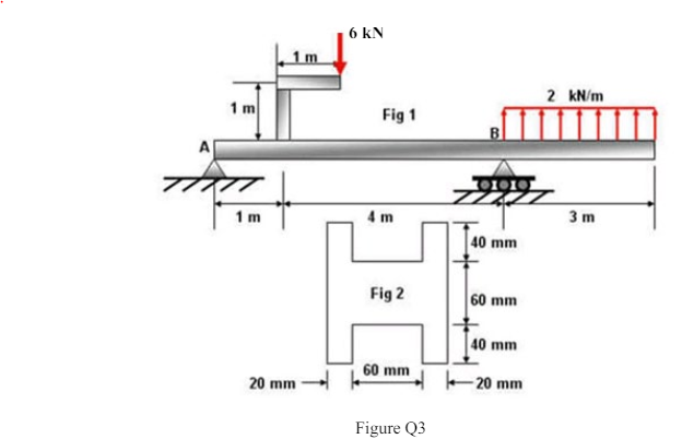
Question 3
A beam is loaded as shown in Figure Q3. It has the cross-section shown in the figure. Determine the maximum bending stress in the beam.
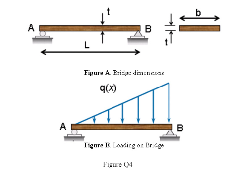
Question 4
A bridge over a stream rests on simple supports. It consists of a single plank of wood with dimensions L = 2.4m long, t = 200mm thick and b = 1m wide (see Figure A of Q4). At a certain time, it carries a distributed load q(x) = 10x kN/m, as shown in Figure B of Q4. Determine the maximum bending moment and maximum bending stress σmax in the beam.
Question 5
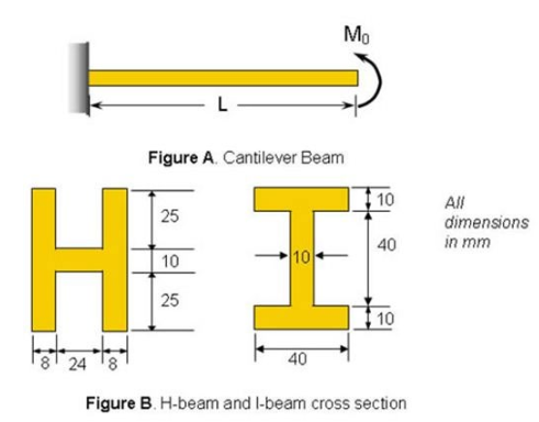
A concentrated moment, M0 = 110 Nm, is applied at the free end of a cantilever (see Figure A of Q5). The beam has a length L = 1.5m and a Young’s Modulus E = 200 GPa. Two crosssections with the same area are proposed for the beam: an H-section and an I-section (see Figure B of Q5). Determine: a) the slopes at the free end of the H-beam and I-beam b) the deflection at the free end of the H-beam and I-beam c) From your answers in (a) and (b) decide if the statement “The I-beam is stiffer than the Hbeam” is true or false.
Question 6
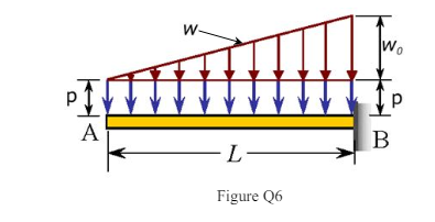
A cantilever of length L = 2.2m is subjected to two loads, namely a uniformly distributed load p and a linearly varying load w(x) as shown in Figure Q6. Determine the magnitude of the deflection and slope at the free end. EIz = 200×104 Nm2 ; p = 1.6 kN/m ; w0 = 3 kN/m.
Question 7
A uniformly distributed load of intensity w =1.5kN/m is applied to a simply supported tubular beam of length L = 3m. A load P is applied at the mid-point B (see Figure A of Q7). The design specifies an allowable deflection of 3.6mm. Determine the maximum value of P. The dimensions of the tube cross-section are shown in Figure B of Q7. E=200GPa.
Buy Custom Answer of This Assessment & Raise Your Grades
Get assignment help in singapore to solve OTH396 Civil Engineering homework task. we have the best team of Homework Helper for singapore students. you can any type of assignment solution at a reasonable price.

Looking for Plagiarism free Answers for your college/ university Assignments.
- CH2123 Assignnment : Fugacity, VLE Modeling & Henry’s Law Applications
- BAFI1045 Assignment -Constructing and Evaluating Passive and Active Portfolios Based on the Straits Times Index (STI)
- PSB501EN Assignment 1: Engineering Systems Integration: A Multi-Technique Approach to Mechanical Analysis
- FIN2210E/FIN2212E Group Assignment: Financial Risk Management Analysis of Bursa Malaysia Companies
- FLM101 Assignment: A Cinematic Dissection: Stylistic Elements and Their Thematic Significance
- Assignment: Transforming Talent in the AI Era: From War to Wealth through Ecosystem Innovation
- COMP 1105 Assignment: Health-Focused E-Commerce Website: A Web Technologies Project Using HTML5, CSS, and JavaScript
- Assignment: Machine Learning in Robo-Advisory Services: Evolution, Applications, and Future Trends
- OMGT2229 Assignment: Quantitative Forecasting, Economic Order Analysis, and Strategic Sourcing Decision-Making for JB Hi-Fi
- Assignment 2: Corporate Finance and Planning: An In-Depth Financial Analysis of Company