| University | RMIT University (RMIT) |
| Subject | MIET1077 Mechanics of Machines |
Use this template to prepare your assignment for MIET1077: Mechanics of Machine
How to use this template:
- Read and follow all the instructions highlighted in yellow colourand delete all highlighted instructions from your final report.
- You must fill out all the tables in the report and replace the figures that are given as examples with your own figures/diagrams.
- You can draw diagrams on A3 or A4 size paper by hand. However, you need to scan them with proper resolution to use them in your report. Save your final report in PDF file format to submit on the Canvas LMS.
- Please see the ‘Assignment Handout’ (available on Canvas) for additional information and suggestions.
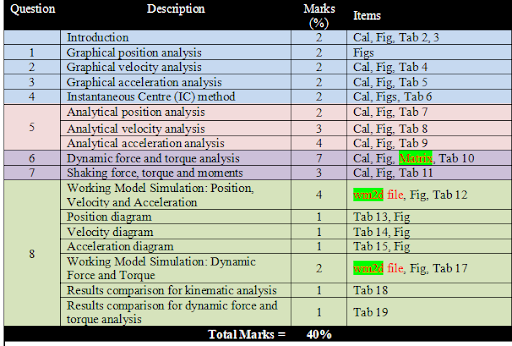
- The detailed marking rubric is given below:
Hire a Professional Essay & Assignment Writer for completing your Academic Assessments
Native Singapore Writers Team
- 100% Plagiarism-Free Essay
- Highest Satisfaction Rate
- Free Revision
- On-Time Delivery
Introduction:
Guidelines for choosing the remaining dimensions of the mechanism:
OE = CD= 4OA
(OA+AB) < (OE+BE)
(OA+OE) < (AB+EB)
AC = 3/5 AB
H = 1/4 OA
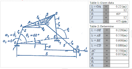
Calculations for choosing the dimensions:
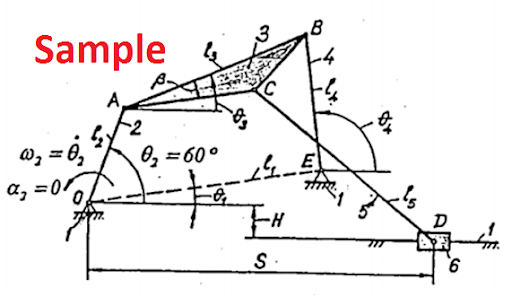
Sample
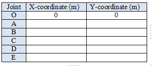
Find out the X and Y coordinates of all the points at θ2 = 60° and fill out the table below
Buy Custom Answer of This Assessment & Raise Your Grades
Answer to question 1:
Determine all possible positions of links and joints by graphical position analysis. Draw to scale all positions of joints for sixteen subsequent positions of link 2 and determine the limits of motion where appropriate. Identify and outline the paths of each moving joint.
[Write your answer here. Show detailed drawing and calculations with proper labelling and scale information]
Draw to scale all position of joints for 16 subsequent positions of link 2 and determine the path of each moving points. [See Figure below for an example]
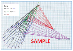
Figure: Position diagram showing 16 points including path of each moving parts (Scale: 1 mm = ?? m)
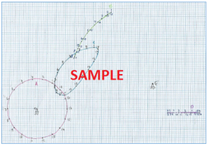
Figure: Position diagram for path of each moving parts (Scale: 1 mm = ?? m)
Answer to question 2:
Determine linear and angular velocities by graphical velocity analysis for the given position q2 = 60° of the mechanism, as shown above. Draw to scale the velocity vector diagram encompassing all linear velocities to scale and present the results in a tabular form.
[Write your answer here. Show detailed drawing and show calculations step by step with proper labelling and scale information]
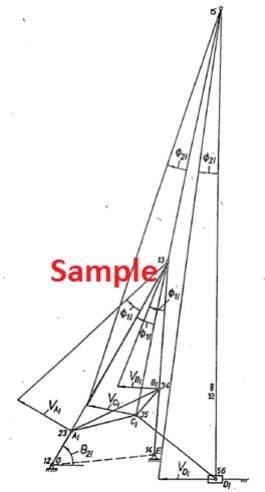
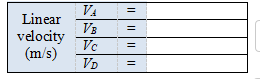
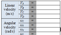
Show the calculations of VA, ω2, ω3, ω4, ω5 and draw to scale the velocity vector diagram of the mechanism at θ2 = 60°. [See Figure below for an example]
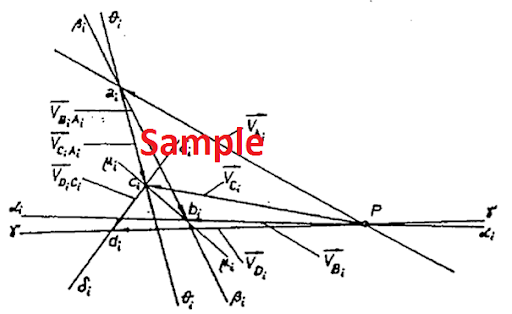
Figure: Velocity diagram (Scale: 1 mm = ?? m/s)
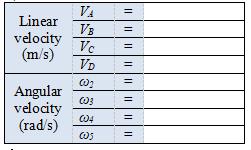
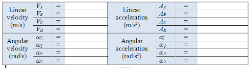
Table 4: Results from graphical velocity analysis\
Show step by step how the Linear velocity (m/s) and Angular velocity
Buy Custom Answer of This Assessment & Raise Your Grades
Answer to question 3:
Determine all linear and angular accelerations by graphical acceleration analysis for the given position q2 = 60° of the mechanism. Draw to scale the acceleration vector diagram encompassing all linear accelerations to scale and present the results in tabular form.
[Write your answer here. Show detailed drawing and calculations with proper labelling and scale information]
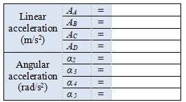
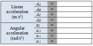
Show the calculations of AA, α2, α3, α4, α5 and draw to scale the velocity vector diagram of the mechanism at θ2 = 60°. [See Figure below for an example]
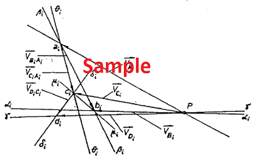
Figure: Velocity diagram (Scale: 1 cm = ?? m/s2)
Tabulate the values from Graphical Acceleration Method in Table 5.
Table 5: Results from graphical acceleration analysis
Answer to question 4:
Determine all instantaneous centres of velocity for the given mechanism using Kennedy’s rule, and velocities of joints A, B, C and D using identified instantaneous centres. Draw all instantaneous centres and velocities to scale on a separate diagram of the mechanism.
[Write your answer here. Show detailed drawing and calculations with proper labelling and scale information]
Find out all the Instantaneous centres of zero velocity using Kennedys triangle theorem and draw them all. Also draw the diagram to scale using Instantaneous Centre (IC) method at θ2 = 60°. [See Figure below for an example]
Tabulate the values in Table 6.
Table 6: Results from graphical velocity analysis (IC method)
Answer to question 5:
Obtain analytic solutions for positions, velocities and accelerations by vector loop equations and complex number notation and present the results in a tabular form. Compare these results with those obtained using the graphical approach. You should have good correlation.
[Write your answer here. Show detailed drawing and calculations with proper labelling and scale information]
- Analytical position analysis:
Find the position (X and Y coordinates) of joint A, B, C, D and E at θ2 =60°. Show the calculations in detail and tabulate the values in Table 7.
Table 7: Positions from analytical method
- Analytical velocity analysis
Find the velocity of joint A, B, C and D at θ2 =60°. Show the calculations in detail and tabulate the values in Table 8.
Table 8: Results from analytical method (velocity)
- Analytical acceleration analysis
Find the acceleration of joint A, B, C and D at θ2 =60°. Show the calculations in detail and tabulate the values in Table 9.
Table 9: Results from analytical method (acceleration)
Answer to question 6:
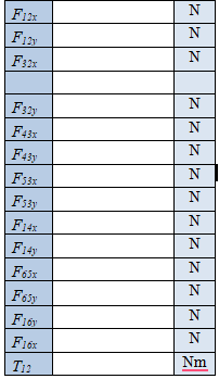
Determine all dynamic forces at the joints for the given position of the mechanism using the analytical matrix method. Assume, for link 2: m2 = 1 kg, CG at OA/2, I2 = 0.002 kgm2; for link 3: m3 = 2.5 kg, CG at b/2 and AB/2, I3 = 0.008 kgm2; for link 4: m4 = 1.5 kg, CG at EB/2, I4 = 0.005 kgm2; for link 5: m5= 1.8 kg, CG at CD/2, I5 = 0.006 kgm2; for slider 6: m6 = 0.9 kg and CG at D.
[Write your answer here. Show detailed drawing and calculations with proper labelling and scale information] [See assignment Handout for figures and formulas]
Derive 14 linear equations and define the Matrix. See an example below:
You can solve the unknown forces and torque using Matrix solver or MS Excel. You must insert a screenshot of your matrix solution and tabulate the values in Table 10.
Table 10: Results from dynamic force and torque analysis
Answer to question 7:
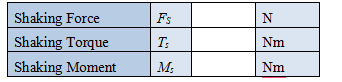
Determine the shaking force, Torque and moment.
[Write your answer here. Show detailed drawing and calculations with proper labelling and scale information]
[Please see the ‘Assignment Handout’ for sample diagrams and calculations]
Table 11: Shaking force, torque and moments
Answer to question 8:
Develop an equivalent computer model capable of simulating the motion of the given mechanism using software Working Model and compute and plot the paths, velocities and accelerations over one revolution of the crank at the given angular velocity w. Also, find the pin forces, slider side loads and driving torque over one revolution. How do the results compare with those obtained using the graphical and analytical approaches?
[Write your answer here. Show detailed drawing and calculations/Screen shot with proper labelling and scale information]
Computational Method:
Using the coordinates of O, A, B, C, D and E from the graphical or analytical method, create a virtual computer model of the linkage mechanism using Working Model simulation software. Define 16 points for 1 full revolution of joint A. Define output for position, velocity and acceleration for Point A, B, C and D. Take a screen capture of the mechanism as shown in Figure 6 for an example. Run the simulation for 1 revolution. Export data from working Model and plot following diagrams: (a) position (see example Figure), velocity (see example Figure) and acceleration (see example Figure) using Microsoft Excel and tabulate the values in Table 8.
- Part-1: Working Model Simulation for Position, Velocity and Acceleration
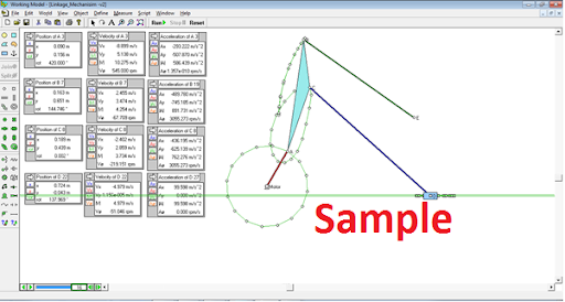
Figure: Working Model simulation for Position, Velocity and Acceleration
Table 12: Results from computational method (Velocity and Acceleration) for θ2 = 60° [after 1 revolution]
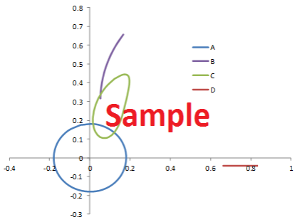
Position diagram:
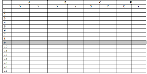
Insert the table of exported data from Working model simulation:
Table 13: Position diagram data
Plot a graph in Excel and insert here. See the example below:
Stuck with a lot of homework assignments and feeling stressed ?
Take professional academic assistance & Get 100% Plagiarism free papers
Are you finding your MIET1077 - Mechanics of Machines assignment challenging? Our assignment help in Singapore is just what you need! Singaporean students can simply pay our expert to do your assignment for you. We offer specialized Engineering assignment help designed for students. Let us help you succeed in your studies today!

Looking for Plagiarism free Answers for your college/ university Assignments.
- ANL303 Data Analysis of Diabetes: Exploring K-Means and Apriori Models for Patient Profiling, GBA
- HRM335 Exploring Leadership Adaptability: Insights from Industry Leaders (GBA)
- ELG101 Linguistic Analysis of Affixes, Word Formation, Syntax, and Social Media’s Impact on Language (TMA02)
- MTH355 Solving Linear Equations and Optimization Using LU Decomposition and Linear Programming, TMA
- PSY352 Cultural Evolution And Persistence in a Changing World, ECA
- CMM315 The Rwandan Genocide and Peacebuilding Efforts, ECA
- HRM335 Reflecting on Leadership Experiences: Connecting Theory to Practice (TMA02)
- MGT568 Agile Leadership in CEO Succession Planning: Strategies for Organisational Success (ECA)
- MGT568 Agile Leadership Scenario Planning: Strategies for Business Resilience
- GSP165 Legal Principles in Divorce, Child Custody & Estate Distribution